|
NEVER ASSUME A LEVEL IS ACCURATE -
ALWAYS CHECK BEFORE USING
There are three main types of instrument that can
be used for carrying out a level survey.
All three do the same job which is to
transfer a level of one point to another or to establish the difference in
height between two points. The differences are in ease of use, accuracy and
number of persons required to operate. There are other methods and instruments,
for example using a spirit level and pegs, but you will most likely be using one
of the above if you wish to complete a survey in a reasonable time.
If you are lucky enough to have a large-scale
ordnance survey map of your area you may be able to pick up a reference level
from that. The levels are marked in the form of a benchmark and represent a
level above sea level, this being the mean sea level at Newlyn in Cornwall. The
actual mark may be on a building, a wall or even a side of a post box.
On a
building site using a level, these benchmarks would be used to obtain the height
above sea level and eventually to specify the height of any building
work.
For our purposes I am assuming that the height of your running
track above sea level is not really an important issue. By ignoring this it can
help to make any working out easier especially if you set your base level so you
do not use negative figures.
Using an Optical
Level
The level kit will include a level, tripod and a
staff.
I am assuming that if you hire a level it would be an automatic
tilting level. In this system a prism is suspended to give a level line of sight
and therefore once set up does not require further adjustment apart from
focussing.
When setting up the tripod first find a suitable spot which
is not going to be in the way of work and gives you a line of sight to the
points you wish to take levels. Set the top of the tripod at around shoulder
height and roughly level. Then place the level on the top and secure using the
screw. Always open the level box on the ground just in case the box is upside
down and the level falls out.
Using the three thumb turns move the bubble in
the circular spirit level on the side of the instrument until it is in the
centre circle.
|

|

An example of an automatic tilting
level |
Looking through the level you will see
lines, called stadia lines. The horizontal line in the centre is the line you
take readings from. If the line is out of focus then sharpen it up by turning
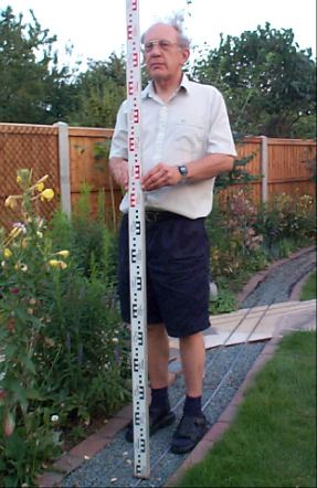
the eyepiece. To take a reading one person needs to look through the level while
one holds the staff. The staff is graduated in 10mm blocks and changes colour
every 100mm. The user of the level will have to estimate to the nearest
millimetre. The staff is placed on the point you want to measure and held
vertically (traditionally by a chain boy).
The reading you take will be the line of sight or
height of collimation. By adding this reading to the height of a known spot you
can then can easily work out levels of other points by deducting the readings.
Recording
Results
There are two main methods of recording and working
out heights (reduced levels). One is the rise and fall method and the other
being the height of collimation. For our purposes the height of collimation is
better as it is easier for multiple readings taken from one point.
First of
all set the level up roughly in the central area of where you will be taking
readings. The first reading called the back sight should be to a known point. If
you do not have a known point select a fixed point such as a door step, corner
of path - something which cannot be knocked and can always be referred back to.
Give this a height say of 10m and call it point A. By giving it a height
(reduced level) of 10m it will avoid the use of negative values (unless your
garden slopes more than 10m).
Point A has a reduced level of 10m. If for
example, you took a reading of 1.800m then the height of collimation will be
11.800m. If we then turn the instrument and take another reading - foresight e.g
point B, 1.750m then we can easily work out the reduced level of point B. HoC -
Foresight = RL 11.800 - 1.175 =10.050m. From this you can see that point B is
50mm higher than A.
Any readings taken in-between back-sight and
fore-sight are called inter-sight.
If you cannot do all your readings from
one position then simply move the level and take a back-sight reading onto the
last fore-sight reduced level. As a cross check, if working over long distances
and transferring from point to point it is worth working back to your initial
point and "close the loop". The reduced level on your starting peg should be the
same at the start and end. Don't worry too much if you are only a few
millimetres out.
Two Peg
Test
Even though the level may have a calibration sticker on
it which is well in date or your best friend swears its fine, do not assume that
it is calibrated and giving correct readings. I cannot stress this enough
especially as I heard of yet another example of a close friend using a level who
came a cropper with a faulty level. These are precision instruments and it only
needs to have been dropped once for any calibration to be come undone. Therefore
it is best to carryout a quick test.
As the name suggests, you need two pegs or
points of reference. These should be a fair distance apart, normally over 30m
and at a fairly similar level. The test works by assuming that if the level is
out of plumb, then by taking a reading in the centre of the two pegs the error
will be the same for both readings.
 |
Left
As long as the distance between the two points and the level are equal
then the error taken in the reading will be equal. Therefore the difference
between the two points can be worked out even if the level is
faulty. |
|
|
 |
If the level is reading correctly the difference between the
two points should be the same as when taking readings with the level in the
centre.
If not, then the difference is the amount the level is wrong by. If this
is significant then the instrument will need
recalibrating. |
Once you have taken the readings deduct
point A from point B. This will give you the difference between the points. Now
move the level to about 1m past peg B. Then take a reading of both points.
Assuming there is negligible error over the distance of 1m, the difference
between the readings should be the same as the first set. If not, The difference
between the two sets of readings will show how much the level is misreading.
It is up to you to decide whether it is accurate
enough to continue using the level but if your readings are only say 5mm out
then you are doing well. Account must be taken of the fact that you are only
estimating to the nearest millimetre and this is open to error.
Unlike
earlier dumpy levels most tilting levels need to be sent away for
calibration.
Rotory Laser
Level
There are several types of levels which use a laser
but for this purpose I am assuming it is a rotary laser level. The kit includes
laser level, tripod, staff and target. DO NOT ASSUME IT IS ACCURATE. All
measuring equipment can fall out of calibration. Some come with a calibration
testing instructions but if not it is worth doing a two peg test.
The
level works using a rotating prism which spins and produces a 360 deg level
beam. It is used in the same way as an optical level but you only need one
person. Readings are taken by holding or clamping the target against the staff.
When the target is hit by the laser it will bleep until you are at the correct
height when the tone becomes continuous. Readings are simply taken by sliding
the target up or down the staff until you reach the correct height. An arrow on
the target will point to where to take the reading on the staff.
Once you
have taken the first reading you can simply go on to the next point without
having to move the level.
Water Level
This usually consists of two optical tubes
and a length of flexible hose connecting them. The level is filled up with water
through one tube until the water level is half way up the tubes are then marked
or if calibrated hold both tubes together and a reading noted. To help prevent
surface tension affecting readings, a little bit of washing up liquid in the
water will help.
To take a reading, one tube is held against a specific
point, usually on a peg. This mark will be of a predetermined height and would
have been transferred from a known point. The other end of the level is then
taken to where you require to take measurements.
The tube is then raised or
lowered until the water level is at the height of the mark (or reading) on the
tube. Then using a ruler or tape measure the distance from the water surface to
the ground is measured. This is repeated for all the points required.
The
water level has the advantage of being cheap and able to work around corners but
does have its drawbacks. It is easy to spill the water by lifting one end too
high or putting it down. Surface tension can also cause problems when reading.
Using The Results of a
Survey
Before you start I am sure you already have a good
idea about where you intend to build your railway. Therefore it is hardly worth
surveying the whole garden as you will mainly be concerned about the gradients
of the railway. For the simplest method it is worth laying a tape measure along
the proposed route and take readings at 1m intervals. These can then be easily
put onto a spread sheet on a computer or easily plotted out to produce a
gradient profile of the route.
From here it can be identified where there are
potential problems and how to solve them.
| Backsight |
Intersight |
Foresight |
H.O.C. |
Reduled Level |
Remarks |
| 1.800 |
|
|
11.8 |
10.000 |
Piont A (wall) |
|
1.755 |
|
|
10.045 |
1m |
|
1.786 |
|
|
10.014 |
2m |
|
1.802 |
|
|
9.998 |
3m |
|
1.809 |
|
|
9.991 |
4m |
|
1.792 |
|
|
10.008 |
5m |
|
1.771 |
|
|
10.029 |
6m |
|
|
1.750 |
|
10.050 |
Point B (peg) |

From the graph it clearly shows a steep rise and fall which with
a little work could be eliminated. Your proposed route and levels can be easily
marked out by hammering in pegs either side of track bed.
By putting the pegs at 1m intervals and say 600mm
from the centre of the track bed work can be carried out without disturbing the
pegs. The height of the top of a peg can be measured and through a simple
calculation the reduced level of the track bed can be measured from the top of
the peg. Alternatively if you are raising the ground, by using a long peg it can
be hammered in until the top is at the required level. A piece of wood laid
between the pegs on either side will give you the height of the track bed
base.
For short distances a spirit level can be
used to transfer and check levels. For long term maintenance putting pegs in
with known heights or marking levels on posts are good way of checking for
ground and track movement.
Next Stage - Basic Masonry
|